


V293 can be installed in the following ESC models:![]() RS SPEC GEN3
RS SPEC GEN3
![]() RS GEN3
RS GEN3
![]() RS PRO 1S Black Edition
RS PRO 1S Black Edition
![]() RS PRO Black Edition
RS PRO Black Edition![]() RSX PRO
RSX PRO
![]() RX4
RX4
![]() RX8 GEN3
RX8 GEN3
V295 can be installed in:
![]() RX8 GEN3
RX8 GEN3

LAUNCH POWER
Choose your desired Launch Power from 1 - 100% and leave the start line effectively and consistently hit after hit. Dial in the Power that best suits your car and racing surface for the perfect launch, every time. Be open minded about what might work best considering many of the fastest people in the country are launching at 30% to 40%.
POWER DELAY
Choose the time it takes for your ESC to reach full throttle after the launch. Fine tune your power profile for your car and racing surface and put down consistent ET's. Start slow and increase as your car can handle it due to traction conditions and car setup.
LAUNCH BOOST
Need a little more pull on that high traction street or strip? Use Launch Boost to increase how aggressive the ESC increases to full throttle. Setting is rpm based so recommended only for high traction and advanced users. Only settings 2 or maybe 3 are useful with low turn motors. Higher settings are useful for 13.5 classes to dial in the power response.
TURBO
Turbo Timing features have been added to Dual Mode. This gives you the ability to set Turbo just like you could on sensored-only setups before that were only available on the RS series ESCs. Now you have the Turbo option all the time!
Improved Data Logging now includes PWM and Battery monitoring, allowing you to see the actual output from the ESC to motor as well as watch battery ripple for signs of a setup that may need changes.
PWM
Pulse Width Modulation, the signals sent from the ESC to your motor to make it go. Recording PWM will show you exactly how the new Launch settings are affecting the output to motor, allowing you to fine tune power over the whole run.
BATTERY
Ripple voltage can indicate problems in a setup and spotlight issues such as an over geared motor, too much timing being added in, timing being added in too quickly resulting in excessive load on the system or a combination of all. This may also indicate a weakened battery or a motor that may have a sensor issue or solder connection issue.

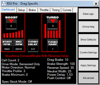
This page provides all the information that you will need to understand your Tekin Brushless ESC settings in the V280 Eliminator drag racing firmware. This will be updated with any changes as needed. We will list the settings per tab as you go through the Tekin Hotwire interface on Windows, Android or Apple.
The Dashboard is a snap shot where you will see all your settings in one place. It’s a great place to take quick look at your settings. You will see this first when plugging into a Tekin ESC.
Note that you can mouse-over on any of the settings labels by simply putting your mouse pointer onto the text of the setting you want to learn more about and dialogue box will pop up explaining the setting.
Once you’re in one of the five tabs you can also right click on any of the sliders to see the corresponding default LED settings. The Dashboard will look different from one ESC to the next as they do not all have the same settings and adjustments available across all platforms.

Dashboard Expanded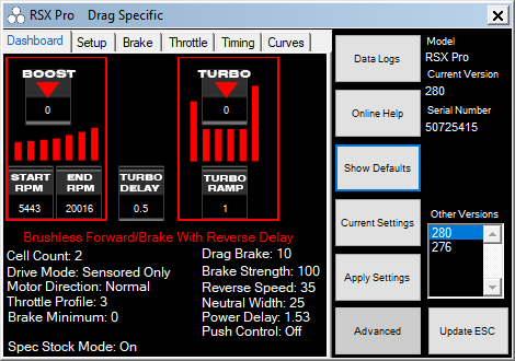
DATA LOGS
The Data Logs button will initiate the Data Logs interface and allow the user to read, download, and save data logs. For more info on this click HERE. As of 15.16.1 with V276, Data Logging is OFF by default. To turn Logging on, click Data Logs to open up the Data Analyzer. Plug your ESC in, click Data, then click Download. When the data loads, it will be blank. Click Logging, then click Sample Rate and choose how frequently you would like the ESC to capture data. Faster rates take up more space, so you may need to adjust the sample rate if you need to record longer logs.
ONLINE HELP
Clicking this button will take you to the Tekin FAQ section of our website.
SHOW DEFAULTS
Clicking this button will show the default ESC settings for the ESC connected. If you want to simply reset the esc clicking on this then Apply Settings will apply the default settings.
CURRENT SETTINGS
Clicking this button will show the current settings programmed into the ESC.
APPLY SETTINGS
Clicking this button will Apply any setting changes that the user may have selected while connected to the ESC.
ADVANCED
Clicking the Advanced button will expand the Hotwire interface allowing the user to see the Current Version of software installed in the ESC. It will also show Other Versions if any are available for the ESC. The current ESC connected will be shown as well as the product serial number. Keep this written down somewhere as it could help you identify your ESC if it is every lost or stolen.
UPDATE ESC
Flashes the selected firmware version to the ESC. Don't click this to save settings as it will reflash the firmware and return the ESC to default settings.

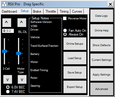
VOLTAGE CUTOFF
The top box that is default 3.2 is the per-cell voltage you can program. By default Tekin sets this to 3.2v which is the industry accepted standard for voltage cut off per cell.
The Slider allows you to set the cell count to the proper setting. 1 for 1 cell, 2 for 2 cell, so on and so forth. Note: we do not have an auto setting so be sure to set the proper cell count.
MOTOR TYPE
This slider allows you to choose what motor drive type you want and your reverse and braking preference.
BL-FW - Brushless FWD/BRK No Reverse
BL-F/R - Brushless Forward to Immediate Reverse
BL-DL - Brushless FWD/BRK/REV Delay
BR - FW - Brushed FWD/BRK No Reverse
BR - F/R - Brushed Forward to Immediate Reverse
BR - DL - Brushed FWD/BRK/REV Delay
SETUP NOTES
This section allows the user to save his/her profile with a full complement of notes. You can then save this profile on your own device, share with others via email, etc.
REVERSE MOTOR
This check box simply reverses the motor direction for models that may require it.
1S LIPO
This check box should be selected anytime the ESC is running with a 1s lipo battery. It will adjust the start/end rpm’s on all preloaded boosted profiles as well as other optimizations in the ESC.
FAN AUTO / ALWAYS ON
These to radio circles allow the user to choose how the fan is controlled. By default as of V255 the fan is always on, which allows the HotWire 3.0 to connect anytime you want. Choosing Fan Auto On will only turn the fan on briefly when powered up, then on as the ESC requires which initiates it at approximately 140F.
BEC
You can choose between a 6V BEC output or go high voltage by selecting the 7.4V BEC option. This can be used to increase servo speed and torque.
ONLINE SETUPS
Clicking this takes you to our website setup page where you can find team drivers setups.
LOAD SETUP
Clicking this will open up a window where all your stored/saved setups are saved (default).
SAVE SETUP
Fill out the “Setup Notes” area and then save your favorite setups right onto your device (Only Windows at this time).
EXPORT SETUP
Clicking this “exports” your current setup to your “My Documents” folder on your device (Only Windows PC at this time).

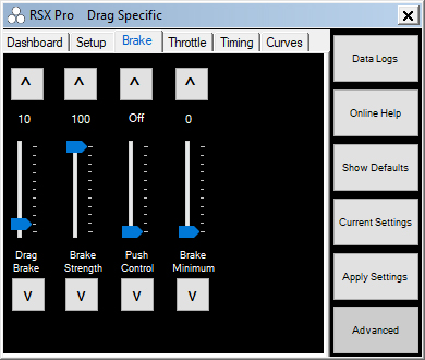
DRAG BRAKE
Drag brake also known as coast brake or auto brake is braking power applied by the ESC anytime the ESC sees a valid neutral signal from the transmitter. The higher the value, the more drag brake is applied. You can drag the slider up/down and or right click to see the default LED settings which you would get from using the on board button selections. Note: on some radios a neutral width setting that is too low may cause erratic Drag Brake operation.
BRAKE STRENGTH
Brake Strength is the total brake power the ESC will provide the motor. Higher values will give more power, vice versa for lower settings.
PUSH CONTROL
Push Control is the opposite of Drag Brake. This setting will add an active amount of creep or coast to the motor. The higher the value, the more push the motor will be given which can negate motor cog torque, excessive drive train drag, or simply help a car gain more corner speed. This setting is only “active” while the ESC receives a valid neutral signal. The longer WOT or wide open throttle is seen by the esc, the more push the user will receive. This allows for slower corners to feel the same as a high speed sweeper. Note: on some radios a neutral width setting that is too low may cause erratic Push Control operation.
BRAKE MINIMUM
Brake Minimum or initial brake is the minimum brake power the ESC will apply to the motor when the user induces a brake application also known as push brake. If you want a stronger initial brake hit use a higher value. Use a lower value or 0 to have a softer brake application.

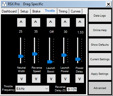
NEUTRAL WIDTH
Neutral Width adjusts the ESC’s sensitivity to the neutral signal the radio system provides. Lower settings will provide a much more sensitive trigger feel. Higher settings will allow for a little trigger travel before engaging throttle or brake. Note: Setting that are too low for a particular radios system may cause erratic Drag Brake, Push Control, or even “arming” issues. If you experience any of these, try increasing your Neutral Width setting first.
REVERSE SPEED
Reverse Speed adjust the amount of power in reverse. Higher values will give more power and speed while in reverse, lower values less power and speed. Note: If Brake Strength is later adjusted using the on board buttons, Reverse Speed settings set via the Hotwire will be discarded.
LAUNCH BOOST
RPM based limiting and increases throttle aggressiveness during the Power Delay period to bring the throttle up to 100% more rapidly. Higher values increase how aggressive the throttle will climb to 100%. Only recommended for very high traction and should be the LAST setting you test with.
LAUNCH POWER
Sets the minimum throttle percentage for launch, 1-100%. As soon as you pull your trigger above what is set on this slider, that value is engaged for the launch. If the value is 55 and you pull 56 or higher on the trigger, the throttle immediately goes to 55% and holds briefly. Lower values hold for less time and higher values hold for more time before Power Delay starts increasing throttle to 100%. This setting allows you to pull and hold full throttle off the line and the ESC does the work.
POWER DELAY
Sets the time in seconds to increase throttle to 100% from the Launch Power value. Example, 1.09 set on the slider means it will take 1.09 seconds to increase throttle to 100% from the set Launch Power value. The Power Delay slider scale changes depending on the Launch Power set, giving you more control over your power curve.
THROTTLE FREQUENCY
Throttle Frequency changes the pulse width being applied during throttle application. In general higher frequencies provide a softer throttle power/feel with a more usable range of trigger motion allowing for better throttle modulation while keeping full throttle power overall. Lower frequency gives stronger throttle with a stronger overall feel.
REVERSE DELAY
Reverse Delay allows the user to choose how long he/she must wait in neutral until reverse power is available to be applied to the motor. The lower the setting, the less time is required to spend at neutral before reverse power is applied. More time will help protect the drive train of the car preventing wear and tear.


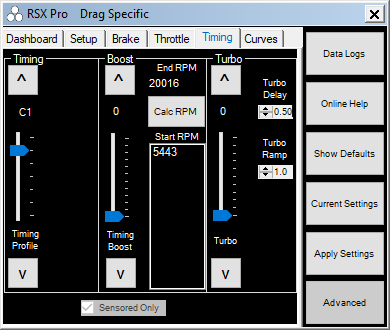
TIMING PROFILE
DUAL MODE
All Tekin brushless ESCs can run in Dual Mode, which uses motor sensors to start the motor smoothly and then switches to sensorless drive at higher RPM for efficiency. The RX4 and RX8 series ESCs are Dual Drive Only controllers, meaning that they do not support sensored-only operation. Turbo and Timing can both be used for up to 30 degrees combined timing advance. There are 7 Timing Profiles available on the RX4 and RX8 controllers with 1-5 increasing sensorless timing advance and C1 and C2 being user-programmable via the HotWire. The Timing Profiles on Dual Drive ESCs work as such:
TP1 - 5° Advance RPM - 5443-20,016
TP2 - 10° Advance RPM - 5443-20,016
TP3 - 15° Advance RPM - 5443-20,016
TP4 - 20° Advance RPM - 5443-20,016
TP5 - 25° Advance RPM - 5443-20,016
TP6 - C1 Sensored Only Custom
TP7 - C2 Dual Mode Custom
TIMING ADVANCE
Increases motor RPM by advancing the timing. 0-30 degrees of timing are available in Dual Mode.
RPM
RPM gives you the option to set the RPM range at which the Timing Advance is applied. Default is 5,443-20,016 and a good place to start with any setup. Choose an End RPM and the software will calculate options for Start RPM values.
TURBO
Turbo is additional timing which is applied to the motor and is activated by the user hitting WOT or wide open throttle once the turbo delay time has expired.
TURBO DELAY
Turbo Delay is the amount of time spent at WOT or wide open throttle the ESC must see form the transmitter before Turbo Timing will be supplied to the motor. Lower delay settings apply Turbo Timing sooner, higher settings provide more delay.
TURBO RAMP RATE
Turbo Ramp Rate is the rate in which your set Turbo Timing value is applied to the motor. Higher values apply Turbo Timing more quickly than lower settings in degrees per second:
1.0 = 2° per .10s
2.0 = 4° per .10s
3.0 = 6° per .10s
4.0 = 8° per .10s
5.0 = 10° per .10s
6.0 = 12° per .10s
7.0 = 14° per .10s
8.0 = 16° per .10s
9.0 = 18° per .10s
10.0 = 20° per .10s
If 20 degrees of Turbo is set to come in at a 1.0 Turbo Delay and Turbo Ramp of 5, that 20 degrees would be added in .20 seconds 1 second after full throttle is reached and held. This gives very precise control over when and how fast your Turbo Timing is added.

TIMING PROFILE SENSORED ONLY
(Available on RX8 GEN3 with V295)
There are 7 default Timing Profiles. RS Series (except RS SPEC) and RSX provide 5 default profiles starting with zero timing spec or blinky mode as well as 4 other Timing Profiles with increasing amounts of boost timing. Timing Profile C1 and C2 are custom user programmable profiles which are stored inside the ESC and allow the user to change from or to these using the on board button interface once they’re programmed. Note that C1 is a Sensored Only profile by default, and C2 is a D2 Dual Mode profile. Sensored Timing Profiles on these ESCs work as such:
TP1 - Blinky Mode No Timing
TP2 - 15° Boost RPM - 5443-20,016
TP3 - 25° Boost RPM - 5443-20,016
TP4 - 35° Boost RPM - 5443-20,016
TP5 - 45° Boost RPM - 5443-20,016
TP6 - C1 Sensored Only Custom
TP7 - C2 Dual Mode Custom
If the user selects one of the two available Custom Timing Profiles you will gain access to additional sliders described below. Timing Profile C1 is a Sensored Only profile and gives the user the following additional Turbo and Boost Timing adjustments. C2 defaults as a Dual Mode profile but can be setup in Sensored Only as well.
BOOST
Boost is additional timing which is applied to the motor using the Start and End RPM’s set by the user. More timing will increase the kV of a motor, less timing or no timing will reduce the kV.
Note: Boost adds to the set timing on the motor, and any Turbo set, increasing Global Timing. Global Timing is all timing adjustments added together: Motor Can Timing + Boost Timing + Turbo = Global Timing. We recommend NO MORE than 60° of timing be used in any application. Excessive timing may cause damage to the motor or ESC and gearing will need to be adjusted to account for the higher RPM. Use with caution.
RPM
RPM gives you the option to set the RPM range at which the Boost is applied. Default is 5,443-20,016 and a good place to start with any setup. Choose an End RPM and the software will calculate options for Start RPM values.
TURBO
Turbo is additional motor timing which is applied to the motor and is activated by the user hitting WOT or wide open throttle once the turbo delay time has expired.
Note: Turbo adds to the set timing on the motor and any Boost set, increasing Global Timing. Global Timing is all timing adjustments added together: Motor Can Timing + Boost Timing + Turbo = Global Timing. We recommend NO MORE than 60° of timing be used in any application. Excessive timing may cause damage to the motor or ESC and gearing will need to be adjusted to account for the higher RPM. Use with caution.
TURBO DELAY
Turbo Delay is the amount of time spent at WOT or wide open throttle the ESC must see form the transmitter before Turbo Timing will be supplied to the motor. Lower delay settings apply Turbo Timing sooner, higher settings provide more delay.
TURBO RAMP RATE
Turbo Ramp Rate is the rate in which your set Turbo Timing value is applied to the motor. Higher values apply Turbo Timing more quickly than lower settings in degrees per second:
1.0 = 2° per .10s
2.0 = 4° per .10s
3.0 = 6° per .10s
4.0 = 8° per .10s
5.0 = 10° per .10s
6.0 = 12° per .10s
7.0 = 14° per .10s
8.0 = 16° per .10s
9.0 = 18° per .10s
10.0 = 20° per .10s
If 20 degrees of Turbo is set to come in at a 1.0 Turbo Delay and Turbo Ramp of 5, that 20 degrees would be added in .20 seconds 1 second after full throttle is reached and held. This gives very precise control over when and how fast your Turbo Timing is added.
DUAL MODE
C2 Timing Profile sets the ESC to Dual Mode. Tekin Dual Mode is a hybrid drive mode that uses motor sensors to start the motor smoothly and then transitions to Sensorless drive at higher RPM for efficiency. This mode is recommended for 4-pole motors and also works great for drag racing applications running motors lower than 4.0T. Sensored Boost and Turbo timing are not available in Dual Mode. Motor can timing is not used in Dual Mode and has no affect on motor RPM.
SENSORED ONLY
Sensored uses motor sensors 100% of the time and allows you to use Timing Boost and Turbo functions.
LOCKED SPEC MODE
Locked Spec Mode disables the ability to change timing profiles using the on board programming buttons and LED tree. This mode also flashes a special neutral signal, using LEDs 3-4-5 blinking rapidly in between temperature readings. This mode is to make it easy for tech to identify that the ESC is in "Blinky" mode and that it cannot be changed without using a HotWire device.

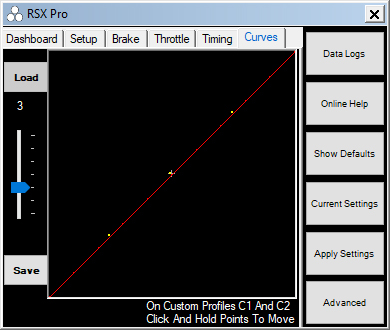
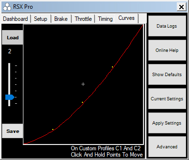
The Curves slider provides 5 preprogrammed throttle curves and comes defaulted in linear profile 3. It also provides two custom profiles you can customize and save.
PROFILE 1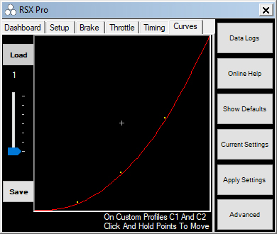
MILD - Profile 1 provides the softest feeling low end and mid throttle. Useful for very low traction situations.
PROFILE 2
MEDIUM - Profile 2 provides a moderate low end and slightly softer mid throttle.
PROFILE 3
LINEAR - Default throttle profile provides linear trigger to throttle relationship.
PROFILE 4
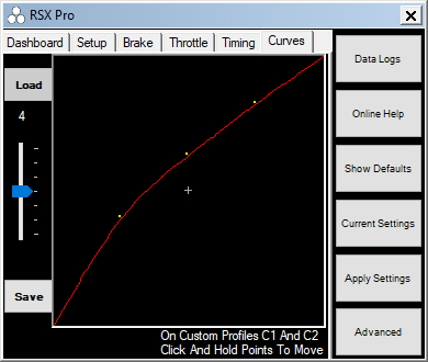
STRONG - Profile 4 provides a slightly more aggressive low end mid range throttle. Useful for higher traction or applications that need a more punchy low end.
PROFILE 5
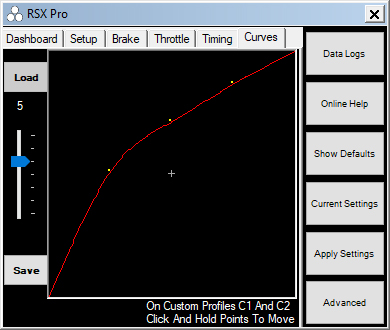
AGGRESSIVE - Profile 5 provides the most aggressive low to mid range throttle feel. Typically used in stock racing applications to provide the most punchy low end.
PROFILE C1
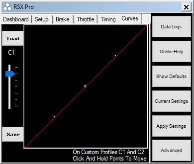
CUSTOM 1 - Allows you to create and save a custom throttle profile by moving the three yellow points up and down on the graph.
PROFILE C2
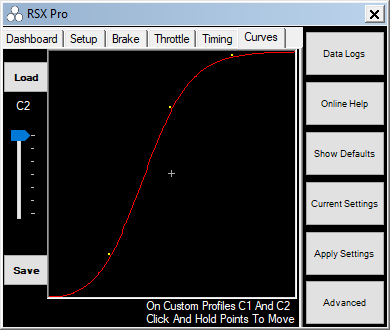
CUSTOM 2 - Allows you to create and save a custom throttle profile by moving the three yellow points up and down on the graph. In this example we have created a SOFT low end, AGGRESSIVE mid range and changed the relationship between the trigger and the throttle position. 50% throttle has been achieved with about 40% trigger pull and 75% throttle at about 50% trigger throw. After 75%the throttle curve starts to level off and that last 25%of the trigger pull controls roughly the last 10% of the throttle. Custom profiles can be created to suit your driving style.